
JSON file
Overview
The simulation of powder bed/substrate fusion is a typical simulation setup, and such simulation preset is available.
All parameters of the simulation can be specified by the user in the input JSON file.
If a parameter is not listed in the JSON file, default values from the default.json are used.
JSON data is written as a comma-separated list of key/value pairs. The list is enclosed in curly brackets. The key and value are separated by a colon(:) in the middle with the key on the left and the value on the right. The key is a string surrounded by double quotation marks. The value can be (1) a number, (2) a string, (3) or JSON data object. With the third option, the JSON data is nested.
Note
The nested field can be referred in the description with dot syntax, i.e. the
{ScanStrategy: {Beam: ... }} field is referred to as ScanStrategy.Beam.
Here are zero level data description. The values of ‘JSON’ data files are detailed in the further sections.
Key |
Value type |
Default value |
|---|---|---|
|
string |
./output/ |
The directory will be created in the current folder. The output data will appear in it during the simulation |
||
|
string |
end-2022-12-31.lic |
Provided with the software |
||
|
JSON data |
|
|
JSON data |
|
|
JSON data |
|
|
JSON data |
|
|
JSON data |
|
|
JSON data |
|
|
JSON data |
|
|
string |
In625 |
Material of the substrate and powder. Chosen from the Materials Library. See Materials |
||
|
string |
null |
|
JSON data |
|
|
JSON data |
|
|
string |
|
Temperature probes file |
||
|
JSON data |
|
|
JSON data |
|
Settings of the internal powder bed generator |
||
|
JSON data |
|
Converter settings for scanning path setting |
||
|
JSON data |
|
Materials library |
||
For convenience, the provided JSON file is annotated.
Some fields are added as comments for the user and are not used in the code.
For example, the fields units and comment that can be found in different sections of the default JSON file are only reference.
Computation Parameters
Here the simulation configuration can be controlled with the parameters in the config section.
Set the maximal number of steps MaxTimesteps or turn on AutoTermination to set upper limit on the simulation time.
If the simulation takes too much disc space, you can increase DumpDataRate, IterationSubstepsRate, turn off DumpVTK, DumpVDB, DumpARR.
If more frames per second are required in the rendered images animation, decrease IterationSubstepsRate.
Other options are for advanced use of the software.
Key |
Value type |
Default value |
|---|---|---|
|
value |
16 |
Number of time steps between grid resize events |
||
|
value |
8 |
The ratio of Tractile Mesh cells coalescing Rate to the cells splitting Rate |
||
|
true/false |
false |
Set to |
||
|
true/false |
false |
The meltpool window is around the beam incidence spot when the beam is turned on. This options allows to link the meltpool Grid with beam center even if the beam power is 0 |
||
|
string |
device |
Where to allocate data. Possible types: device, host, managed |
||
|
value |
1 |
Internal use only. Doesn’t make sense in the release |
||
|
value |
1000 |
Number of time steps after which program statistics and diagnostics functions are called |
||
|
true/false |
true |
Flag to include the curvature and wetting simulation |
||
|
true/false |
true |
Flag to include the evaporation process |
||
|
true/false |
true |
Flag to include the convection process |
||
|
true/false |
true |
Flag to include the ray tracing process |
||
|
true/false |
true |
Flag to include the thermal process |
||
|
true/false |
false |
Flag to setup isothermal Boundary Conditions at x an y boundaries (\(T=\) preheating) |
||
|
NA |
|
Flag to include gas physics (this solver is supplied separately) |
||
|
true/false |
false |
Flag for the parameter, specific for the gas solver simulation |
||
|
value |
10 |
|
value |
1000 |
In the simulation, the high-resolution Meltpool grid follows the melted liquid. Sometimes, small droplets are ejected from the meltpool and fly across the domain; sometimes, some liquid droplet takes too long to cool down and solidify. In these cases, the meltpool grid becomes larger, and time cost for an iteration becomes too large. Check the |
||
|
true/false |
false |
Flag to enable the bubble simulation: correct pressure for the gas trapped by liquid and pore formation |
||
|
true/false |
false |
Flag to enable the grains growth solidification based on the Cellular Automata model |
||
|
true/false |
true |
Terminate simulation with error if the meltpool reaches the limit box or if the Bound grains are reached by liquid cells |
||
|
string |
Temperature |
The solidification process criteria besed on the temperature either on the grain growth Cellular Automata model. The possible values are Temperature and GrainsCA. |
||
|
true/false |
false |
Flag to enable calculation temperature gradients and cooling rates at solidification; resulted 3D data will be stored in the |
||
|
value |
1000000000 |
The maximal number of the time steps. The required number of the steps can be estimated as, i.e. |
||
|
true/false |
true |
Turn on for automatic termination of simulation when scanning is finished and all liquid cells are solidified |
||
|
value |
100000 |
3D data dump rate (time steps). 3D data files take disc space and writing to disc takes time, so it should not be frequent |
||
|
value |
1000 |
Frequency of all other outputs: images, probes, etc. |
||
|
true/false |
true |
Set false if you do not need to save VTK files with tractile mesh temperature and velocities of meltpool. This can save disk space. |
||
|
true/false |
true |
Set false if you do not need to save OpenVDB file geometry.vdb |
||
|
true/false |
false |
Set false if you do not need to save ARR files |
||
Simulation domain and Substrate Sizes
The sizes section defines full simulation domain size.
The fluid dynamics simulation takes place only around the meltpool area.
The meltpool area is allowed to move inside the bounds that are specified here.
Key |
Value type |
Default value |
|---|---|---|
|
value |
0.007 |
|
value |
0.002 |
|
value |
0.003 |
An upper estimate of the simulation domain size (m). This is the sizes recorded in the geometry grid, the size of the volume in the |
||
|
value |
0.0025 |
Substrate thickness (m). The simulation domain from \(z=0\) to \(z=\) |
||
|
value |
0.0 |
z-coordinate of the lower boundary of the substrate |
||
|
list of values |
[[0, 0, 0], [1, 1, 1]] |
An array of the two coordinates (m): the two corners of the Limit box where the grains are initialized |
||
Numerical Parameters
The NumericalParams section defines the mesh cell size and units for nondimensionalization of time, mass and temperature.
Key |
Value type |
Default value |
|---|---|---|
|
value |
3e-06 |
Mesh cell size (m). Should be much less than the smallest particle in the powder, meltpool depth and height. See recommended values |
||
|
value |
3e-08 |
Time step size (s). See recommended values |
||
|
value |
1e-14 |
Mass unit (kg). In the numerical model, if \(m=1\) in the dimensionless units, the physical mass is \(m=\) |
||
|
value |
1000.0 |
Temperature unit (K). In the numerical model, if \(T=1\) in the dimensionless units, the physical temperature is \(T=\) |
||
Powder
In the KiSSAM simulation, the geometry of the powder particles is input through a VDB file.
If the powder is defined with sphere coordinates and radii, it should be rasterized with the provided script.
In the Powder section of the JSON file, the input VDB file is specified, and the wetting angle of powder particles, which is, in general, different from the wetting angle of the substrate.
Key |
Value type |
Default value |
|---|---|---|
|
string |
|
The name of the VDB file with input solid geometry. |
||
|
value |
120 |
Wetting angle of melt contacting with powder particles (degrees). |
||
|
NA |
|
Powder components weight composition with names, eg {“name1”: 0.3, “name2”: “balanced”}, If null than the values from MaterialLibrary will be used |
||
|
value |
0 |
Concentration of the initial grains in the substrate (1/m³) |
||
|
NA |
|
The file with the initial position and size of the filler particles |
||
|
list of values |
[[0, 5e-06], [100, 5.001e-06]] |
|
value |
5 |
Settings for the initial distribution of the filler particles |
||
Substrate
The substrate settings are in the Substrate section.
All other properties of the substrate material are defined through the Material setting.
Key |
Value type |
Default value |
|---|---|---|
|
value |
300.0 |
Preheating temperature of the substrate (K) |
||
|
value |
0 |
Wetting angle of the melt contacting with substrate (degrees) |
||
|
NA |
|
dictionary — Substrate components weight composition with names, eg {“name1”: 0.3, “name2”: “balanced”}. If null than the values from MaterialLibrary will be used |
||
|
string |
|
Path to the file with the initial geometry. Leave empty for flat geometry. |
||
|
value |
100000000000000.0 |
Concentration of the initial grains in the substrate (1/m³) |
||
Camera
The surrounding gas parameters in the chamber are defined in the Camera section.
Key |
Value type |
Default value |
|---|---|---|
|
string |
Ar |
The gas material is specified as one of the keywords for the materials in the Materials section. |
||
|
value |
100000.0 |
|
value |
300.0 |
|
value |
1.0 |
Gas fluid parameters: pressure (Pa), temperature (K) and flow speed (m/s). Flow velocity is used in the Whitaker convection model. |
||
|
value |
0.0 |
|
value |
0.0 |
|
value |
0.0 |
Initial gas velocity (m/s) is used in the RKDG gas solver if |
||
Scanning Strategy
The scanning strategy is defined in the
ScanStrategy.
section of the JSON file.
There are three presets: single track and square layer, and a manual input for the scan path.
Key |
Value type |
Default value |
|---|---|---|
|
string |
SingleTrack |
Scanning strategy preset. Can be |
||
|
value |
0 |
Delay time in seconds for dot pitch scanning also known as digital pitch scan. Set 0 for continuous scan. Works for al types of the scanning strategy presets. |
||
|
JSON data |
|
Description of the Single Track scanning strategy. |
||
|
JSON data |
|
Description of the Square Layer scanning strategy. |
||
|
JSON data |
|
Manual setting of an arbitrary scanning strategy |
||
|
JSON data |
|
Single Track
In this preset, laser beam turns on in the startPosX, startPosY position, travels parallel to the \(x\)-axis with the speed defined in the Beam section, and turns off when the travel distance is over the defined length.
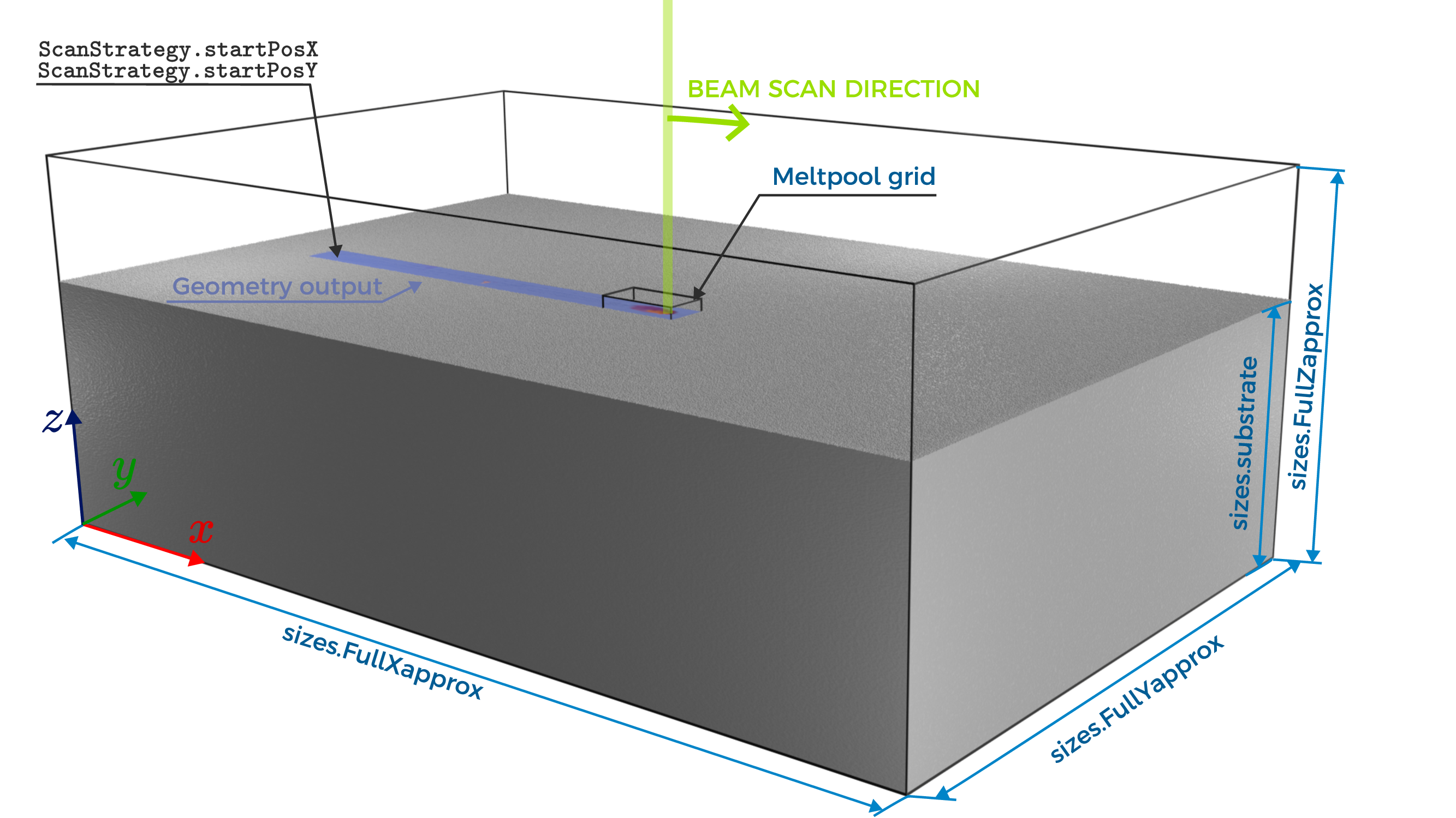
Fig. 5 Single Track Scan Path
Key |
Value type |
Default value |
|---|---|---|
|
value |
0.005 |
Track length (m) |
||
|
value |
0.001 |
|
value |
0.001 |
Starting position (m) of the laser in the simulation domain. It should be inside the domain defined with sizes.FullXapprox, sizes.FullYapprox. If the powder is inside the domain, the starting position of the laser should be in the domain covered by the powder. |
||
Square Layer
The settings of a square layer simulation.
In this preset, laser beam turns on in the startPosX, startPosY position.
If hatchX (hatchY) is zero, the beam
travels parallel to the \(x\)-axis (\(y\)-axis) until the travel distance is over dimX (dimY),
then waits for delayBetweenTracks seconds,
then it shifts by hatch distance and travels for the same distance in the opposite direction.
The scanning speed is defined in the Beam section.

Key |
Value type |
Default value |
|---|---|---|
|
value |
0.001 |
|
value |
0.001 |
Starting position (m) of the laser in the simulation domain. It should be inside the domain defined with sizes.FullXapprox, sizes.FullYapprox. If the powder is inside the domain, the starting position of the laser should be in the domain covered by the powder. |
||
|
value |
0.003 |
|
value |
0.003 |
Square layer dimensions (m). Can be negative. If the laser position is \(x>\) |
||
|
value |
0 |
|
value |
0.00015 |
Hatch distance. To set the scanning speed vector parallel to the \(x\)-axis, set |
||
|
value |
0.0 |
Delay time between tracks (seconds) |
||
Manual Scan Path
If XYpositions is set as scanning strategy, a set of points is read either from a source file, or from a set of points.
Here is an example of an input file.
The first column is time (s), the second and third columns are \(x\) and \(y\) positions of the laser at that time.
The fourth and fifth columns are optional. They contail laser power (W) and laser spot width (m) at that point correspondingly.
If the power and width columns are missing, they are taken as constant (in time) values from the ScanStrategy.Beam section.
0.00   1e-3  1e-3  300 100e-6
2.e-3  3e-3  1e-3  300 200e-6
3.e-3  3e-3  2e-3  300 200e-6
4.e-3  2e-3  2e-3  300 100e-6
5.e-3  2e-3  1e-3  300 100e-6
6.e-3  1e-3  1e-3  300 100e-6
Some examples are available here
If the strategy is set with a pointsArray instead of the input file, the array contains the rows of this file.
Key |
Value type |
Default value |
|---|---|---|
|
NA |
|
Filename of the input data. Set Null to use |
||
|
list of values |
[[0, 0.001, 0.001, 300, 90], [0.001, 0.002, 0.001, 500, 90]] |
Defines scanning strategy if |
||
The source file can be generated from g-code with the builtin G-code converter.
The script uses the same json for the input. The following fields are used in the script. All of the fields are in the G-code-converter section of the JSON.
Key |
Value type |
Default value |
|---|---|---|
|
value |
7000 |
Scan speed to the coordinate of G0 code in mm/sec |
||
|
value |
850 |
Scan speed to the coordinate of G1 code in mm/sec |
||
|
list of 2 numbers |
[25,25] |
offset in mm |
||
Beam Setting
The energy source parameters are set in the ScanStrategy.Beam section.
Key |
Value type |
Default value |
|---|---|---|
|
string |
Laser |
Source type: |
||
|
string |
Gauss |
Beam shape: |
||
|
value |
300.0 |
Laser or Ebeam Power (W) |
||
|
value |
0.0001 |
The Gaussian pulse D4s parameter (m) |
||
|
value |
1.0 |
Scanning Speed (m/s) |
||
|
list of values |
[0, 0, -1] |
Direction vector (three coordinates) to set the incident angle of the beam |
||
|
string |
beamshape.dat |
string — Filename with text lines X-coordinate,Y-coordinate,Power representing the beam shape profile used for “Manual” beam Shape. See more |
||
|
value |
120000.0 |
For electron beam, electrons energy (eV) |
||
|
value |
0 |
For electron beam, set to 0 if electrons are not tracked in the backwards direction |
||
|
value |
1 |
The number of rays per cell in the ray tracing model, must be the perfect square |
||
The shape file format is as follows:
 #Xcoordinate,m       Ycoordinate,m   Power
-0.0002 -0.0002 0
-0.0002 -0.000199 0
-0.0002 -0.000198 0
-0.0002 -0.000197 0
-0.0002 -0.000196 0
-0.0002 -0.000195 0
-0.0002 -0.000194 0
-0.0002 -0.000193 0
-0.0002 -0.000192 0
 ...
Sensors
Settings for the sensors of backscattered electrons and radiation sensors.
See more in Sensors.
The Sensors section can contain the two fields: Default and Array.
Default is a default setting for every sensor that is added to the simulation.
Array is an array. For every element of an array, a sensor is added to the simulation.
Every element should be represented by JSON data with the same fields that are present in the default sensor.
If any field is not specified, the default value is taken.
Key |
Value type |
Default value |
|---|---|---|
|
list of values |
[0, 0, 0] |
Sensor position, three coordinates, m. Works both for electron and radiation detectors. |
||
|
list of values |
[0, 0, -1] |
A vector for the sensor direction, three coordinates. Works for the radiation detectors. |
||
|
list of values |
[8e-07, 1.5e-06] |
An array of 2 numbers. Sensor wevelength band, min and max limits, m. Works for the radiation detectors. |
||
|
value |
0.1 |
Sensor aperture angle in radians. Works for the radiation detectors. |
||
|
value |
0.01 |
Resolution angle of sensor (angle between traced rays from the sensor), the value should be much less than the aperture. Works for the radiation detectors. |
||
|
value |
0.001 |
Sensor size, m. The radius of the sensor is Size/2. Works for the electron detectors. |
||
|
string |
Radiation |
The type of the detector: Radiation or Electrons. Both kinds of the detectors can be present in the simulation. |
||
Visualization
The image output parameters are set in the Visual section.
Key |
Value type |
Default value |
|---|---|---|
|
true/false |
true |
Render or not the 3D images of the region beyond the meltpool grid which are saved in ‘rendered3D’ directory |
||
|
value |
0.0005 |
Distance between \(x=const\) cross-sections (m). |
||
|
list of values |
[0.002, 0.0015, 0.0005] |
Box size (m) for 3D renders output. Set larger than the meltpool grid to see the whole meltpool grid. Set smaller for faster rendering. |
||
|
value |
0.0003 |
|
value |
0.0003 |
Minimum distance from the beam to the visualization box boundary (m) along X- and Y-axes. If this distance becomes smaller than specified parameter, then the vizualization box will be shifted along X-(Y-)axis. |
||
|
list of values |
[0, 1] |
array of 2 numbers — Minimum and maximum limit of wt.part for component1 at cross-section images |
||
Physical World
The section includes the gravity parameter and the choice of the evaporation model
Key |
Value type |
Default value |
|---|---|---|
|
value |
9.8 |
Gravity acceleration in m/s² |
||
|
string |
Whitaker |
Convection cooling model, possible types are |
||