Beam Shape Settings
Introduction
The shape of the laser beam spot is one of the controllable parameters in LPBF. In KiSSAM, any shape of the energy source can be used.
There are pre-defined common shapes. These can be set in the Beam Setting.
Common Beam Shapes
The most common beam shape is Gaussian. A Gaussian beam with \(D_{4\sigma} = 100\) μm is set as follows:
"ScanStrategy": {
  ...
  "Beam": {
    "Shape"    : "Gauss",
    "Width"    : 100e-6,
    ...
  }
},
...
Custom Beam Shape
Any beam shape can be defined manually as follows:
"ScanStrategy": {
  ...
  "Beam": {
    "Shape"    : "Manual",
          "ShapeFile": "beamshape.dat",
    "Power"    : 300.0,
    ...
  }
},
The ScanStrategy.Beam.ShapeFile is a path to a text file with the following format
x,[m] y,[m] Intensity,[a.u.]
where x, y are set in the local coordinate system (the origin is moving according to the scan strategy),
intensity is the laser power per unit surface.
The total laser power is taken from the ScanStrategy.Beam.Power field.
Let us take ring modes as an example. The intensity of shaped laser beam is expressed as follows
where \(m\) is the mode number (\(m=0\) corresponds to the Gaussian beam where ScanStrategy.Beam.Width \(=4\sigma\)),
\(r\) is distance from the laser focus, ), P is the laser total power
For such beam shape, beam width is expressed as follows
Here are the files which are prepared to simulate such beams:
zeroth,
second,
fourth modes
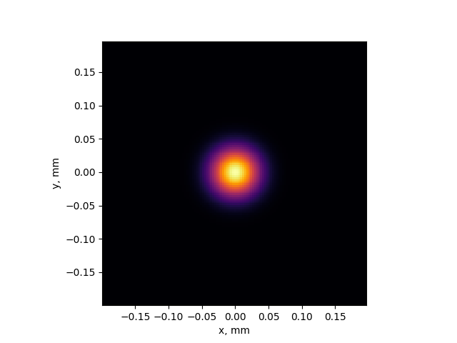
Fig. 16 The zeroth ring mode (Gaussian beam)
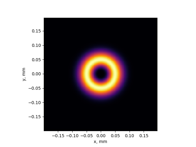
Fig. 17 The second ring mode
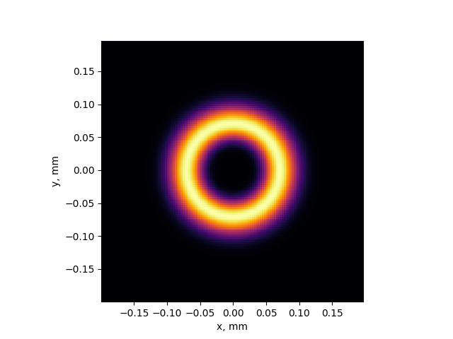
Fig. 18 The fourth ring mode
Here is a quick illustration of how the laser spot shape can influence the result. We simulate one laser track over the Inconel 625 flat substrate with two shapes of the laser spot: Gaussian and ring mode with \(m=4\). The laser power is 600 W, scanning speed is 0.4 m/s.
Here is the setup of the sample simulation. For the ring mode,
{
  "NumericalParams": {
    "dr"       : 3e-6,
    "dt"       : 30e-9
  },
  "sizes": {
    "FullXapprox": 0.007,
    "FullYapprox": 0.002,
    "FullZapprox": 0.003,
    "substrate"  : 0.002
  },
  "Substrate": {
    "preheating"  : 300.0,
    "wettingAngle": 10
  },
  "Material": "In625",
  "ScanStrategy": {
    "Beam": {
      "type": "Laser",
      "Shape": "Manual",
      "ShapeFile": "beamshape_4.dat",
      "Power": 600,
      "Speed" : 0.4
    },
    "SingleTrack": {
      "length": 0.005,
      "startPosX": 0.001,
      "startPosY": 0.001
    },
    "Type": "SingleTrack"
  },
  ...
}
For the Gaussian beam, the shape is set as Gaussian and the width is 0.000224 m.
At the starting point, the shape of the meltpool corresponds to the ring mode:
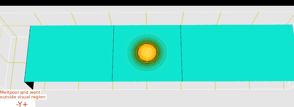
Fig. 19 The Gaussian beam spot, \(t=30\) microseconds
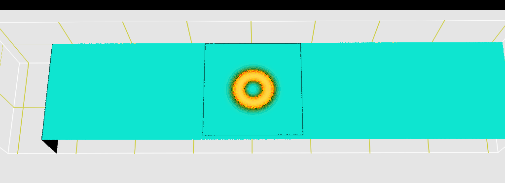
Fig. 20 The fourth ring mode, \(t=30\) microseconds
The simulation result shows, that, after solidification, there is little difference in the track depth and width, but a notable difference can be seen in the shape of the cross-section of the remelted track.

Fig. 21 The cross-section of the remelted track at \(x=2\) mm from the track start for the ring mode and the Gaussian beam