
Powder Layer Generation
Goal
In this example, simulation of a single track on a powder layer is performed. Here, we illustrate how powder is generated before the simulation and used in the simulation. The full instructions can be found here.
In other examples, the powder layer was generated in advance. It is often convenient, since powder generation make take significant time (depending on the layer area and height). Instead of generating powder each time, the layer geometry may be reused for batch simulation of layer or single track melts.
In this example, we take a plate of In625. The laser beam with normal incidence melts the metal in a single track. The beam power is 450W.
You will need the JSON file provided with the usercase.
Prepare the Powder Layer
Create simulation folder
> mkdir simulation_folder
> cd simulation_folder
Copy the JSON file provided with the usercase into the folder
> mv <path>/MakePowder.json .
Run the code from terminal with the provided JSON file.
> /share/bin/PowDEM MakePowder.json -n
Or, if you obtained the docker distribution,
docker run --gpus all -e USER_ID=$(id -u) -e GROUP_ID=$(id -g) -e --rm -v .:/calc -it kissam "PowDEM MakePowder.json -n"
If your system supports GL graphics, you can omit the -n option in the end to see the powder simulation visualization in real time .
Make sure that simulation is started by making sure there are no fatal errors and the simulation progress is visible in the terminal.
The powder_evolution.log file should have appeared in the directory.
It might be necessary to insert the correct license filepath in the JSON file.
Input Configuration
While the simulation is running, let us look at the configuration file and see how it may be adjusted.
The simulation parameters can be adjusted by editing the JSON file.
 1{
 2  "PowderBedGenerator": {
 3    "GroundSurface": "",
 4    "KnifeZposition": 0.00258,
 5    "RandomSeed": 0,
 6    "Type": "PowDEM",
 7    "PSDsizes": [
 8            [
 9                0,
10                2.5e-05
11            ],
12            [
13                25,
14                3e-05
15            ],
16            [
17                40,
18                4e-05
19            ],
20            [
21                100,
22                8e-05
23            ]
24        ]
25
26  },
27  "Powder": {
28    "initSpheresVDBfile": "init_spheres.vdb"
29  },
30  "ScanStrategy": {
31    "Beam": {
32      "Power": 450.0,
33      "type": "Laser"
34    },
35    "SingleTrack": {
36      "length": 0.003,
37      "startPosY": 0.001
38    },
39    "Type": "SingleTrack"
40  },
41  "config": {
42    "AutoTermination": true,
43    "DumpARR": false,
44    "DumpDataRate": 3000,
45    "DumpVTK": false,
46    "IterationSubstepsRate": 1000,
47    "MaxTimesteps": 120000
48  },
49  "licenseFile": "kissam-end-2025-dec.lic",
50  "sizes": {
51    "FullXapprox": 0.005,
52    "FullYapprox": 0.002,
53    "FullZapprox": 0.003,
54    "substrate": 0.0025
55  }
56}
57
58
59
This is the one configuration file which is used both in the powder preparation process and melting simulation process.
The powder setup is found in the PowderBedGenerator section:
"PowderBedGenerator": {
  "GroundSurface": "",
  "KnifeZposition": 0.00258,
  "RandomSeed": 0,
  "Type": "PowDEM",
  "PSDsizes": [
          [
              0,
              2.5e-05
          ],
          [
              25,
              3e-05
          ],
          [
              40,
              4e-05
          ],
          [
              100,
              8e-05
          ]
      ]

}
The Type is the program used to generate powder, the GroundSurface is empty so that the powder is deposited on the flat surface.
The position of the substrate is found in sizes.substrate).
"sizes": {
  "FullXapprox": 0.005,
  "FullYapprox": 0.002,
  "FullZapprox": 0.003,
  "substrate": 0.0025
}
Here, the z-axis position of the substrate is 1mm, and the domain size in \(z\) direction is 2 mm. The PowderBedGenerator.KnifeZposition is between them: 1.15 mm.
The estimated powder layer height is, therefore, 150 microns.
Warning
The sizes section is not optional in the input JSON file if the powder generation is required. In other cases, the sizes are taken from the default configuration, but the PowDEM utility requires this section to be present explicitly.
The powder size distribution PSDsizes is set in the form \([[p_1,d_1],[p_2,d_2], ...]\), where \(p_i\) is the volume fraction of powder particles which have diameter less than \(d_i\). The pairs should be listed in order of increasing diameter.
Simulation Results
Let us look at the intermediate output:
Knife height is 0.08 mm, domain area is 10.2574 mm^2
Substrate set, substrate sizes are: X in [0, 5.088] mm, Y in [0, 0] mm, Z in [0, 2.016] mm.
Processing the PSD data...
PSD percents: 0% 25% 40% 100%
PSD sizes: 25um 30um 40um 80um
Min particle radius=13.75 um
Max particle radius=30 um
PSD by mass (or volume) will be used.
Mean (median) particle radius=13.75 um. Most particles in the initial distibution are of this radius.
18841 particles are of radius Ri=13.75
5483 particles are of radius Ri=17.5
4354 particles are of radius Ri=30
Total number of particles is 28678
As estimated in the previous section, knife height above the substrate is 0.08 mm.
Minimal and maximal particle sizes are shown.
The minimal particle size should be greater than the mesh step in the simulation for correct representation of the geometry in the simulation.
In the current file, the mesh size is not specified, so the default mesh size is used: NumericalParams.dr\(=3\) micron.
The particle size is double its radius: 27.5 micron.
The maximal particle size should be less than the knife height (80 microns). Otherwise, the bigger particles are dragged by the knife and the powder layer is uneven.
Here, the maximal particle size is 60 microns.
In the simulation, the particles fall onto the substrate, and then the knife starts moving with velocity \(v=(2,0,0)\). Here is the sample terminal output for the progress:
Simulation is running...
t = 568.469, starting the knife movement with V = 2
t=999.985. Knife position x=863.086 um. Intermediate output is done!
t=2000.06. Knife position x=2863.24 um. Intermediate output is done!
t=3000.12. Knife position x=4863.37 um. Intermediate output is done!
t=4000.2. Knife position x=3312.65 um. Intermediate output is done!
t=5000.21. Knife position x=1312.61 um. Intermediate output is done!
t=6000.27. Knife position x=-687.492 um. Intermediate output is done!
INFO: Finishing the simulation...
After the simulation is finished, the particles positions and radii are in the spheres.dat file:
13.7468 13.7461 13.7452 13.75
56.2579 13.748 13.7479 13.75
34.9982 36.6536 44.3645 30
13.7488 59.5702 13.7486 13.75
71.4688 13.7499 36.6576 13.75
66.1289 39.415 13.749 13.75
95.7943 17.9657 17.4991 17.5
77.069 46.7592 37.8858 13.75
118.693 13.7472 38.3409 13.75
94.5042 26.21 53.7061 17.5
Here the first three columns are x, y, z coordinates and the fourth column is the particle size.
Powder Preparation for Melting
The particles data should be converted to the simulation mesh volume data.
First, you need to confirm the mesh size in your simulation.
In the current file, the mesh size is not specified, so the default mesh size is used: NumericalParams.dr\(=3\) micron.
Second, run the following command:
/opt/KiSSAM/scripts/rasterizeSpheres.x 3 spheres.dat
Or, if you have obtained KiSSAM via docker,
docker run --gpus all -e USER_ID=$(id -u) -e GROUP_ID=$(id -g) -e --rm -v .:/calc -it kissam "rasterizeSpheres.x 3 spheres.dat"
In this command, the number 3 is the mesh step in microns that we use in our simulation.
After the successful run of the script, the init_spheres.vdb file is generated. Let us inspect it.
3D view of the Powder
The init_spheres.vdb file is in the usual VDB format.
The FillingFrac grid contains the powder geometry.
View it with Blender or vdb_view:
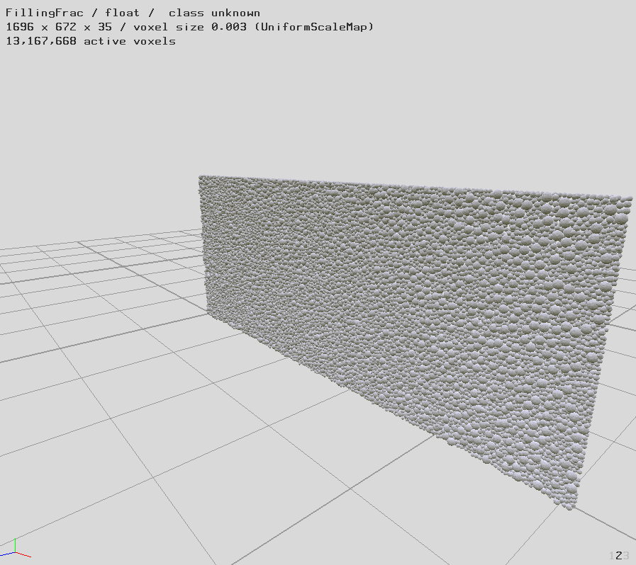
We can inspect that the layer is good quality without irregularities, such as sparse areas.
Run the Simulation
Note that in the input file, the Powder.initSpheresVDBfile is already filled in to the correct filename of the generated powder file:
"Powder": {
  "initSpheresVDBfile": "init_spheres.vdb"
},
Therefore, we can immediately run the simulation:
INPUT_JSON_FILE=MakePowder.json /opt/KiSSAM/start_calc.sh
Or, if you have obtained KiSSAM via docker,
docker run --gpus all -e USER_ID=$(id -u) -e GROUP_ID=$(id -g) -e INPUT_JSON_FILE='MakePowder.json' --rm -v .:/calc -it kissam
The powder layer is placed onto the substrate and the laser melting simulation begins.
Simulation Result
Let us look at the geometry.vdb after the simulation is complete

We can observe the powder layer, that was generated before, melted by the laser and solidified in a new geometry.