
Laser Hatched Layer with Powder Layer
Goal
A powder bed over a plate of SS316L is taken as an initial geometry. The Gaussian laser pulse with normal incidence melts the metal, and hatches a layer.
Powder generation is possible in KiSSAM, but it takes simulation time. When powder is set on a flat substrate, the same powder can be reused in different simulations. In this sample simulation, we use powder layer that was generated before. It should be in a vdb format, with mesh size that corresponds to the simulation setting.
Run
Copy the JSON file provided with the usercase into the simulation folder, and the powder layer file, into the simulation folder.
> cp <path>/Laser_layer_powder.json .
> cp <path>/init_spheres.vdb .
Run the code from terminal with the provided JSON file. You may need to edit the information on the license file in it.
> INPUT_JSON_FILE=Laser_layer_powder.json /opt/KiSSAM/start_calc.sh
Make sure that simulation is started by making sure there are no fatal errors in the .log file that has appeared.
It might be necessary to insert the correct license filepath.
Input Configuration
The simulation parameters can be adjusted by editing the JSON file.
 1{
 2  "licenseFile": "/licences/kissam-end-2023-6-30.lic",
 3  "outputDir": "./output/",
 4
 5  "config": {
 6    "MaxTimesteps"         : 2000000,
 7    "AutoTermination"      : true,
 8    "DumpDataRate"         : 500000,
 9    "IterationSubstepsRate": 1000,
10    "DumpVTK"              : true,
11    "DumpVDB"              : true,
12    "DumpARR"              : false
13  },
14  "sizes": {
15    "FullXapprox": 0.003,
16    "FullYapprox": 0.003,
17    "FullZapprox": 0.005,
18    "substrate"  : 0.00456
19  },
20
21  "Powder": {
22    "initSpheresVDBfile": "init_spheres.vdb",
23    "wettingAngle": 150
24  },
25
26  "Substrate": {
27    "preheating"  : 300.0,
28    "wettingAngle": 10
29  },
30  "Material": "SS316L",
31  "ScanStrategy": {
32    "Type": "SquareLayer",
33    "SquareLayer": {
34      "startPosX": 0.5e-3,
35      "startPosY": 0.5e-3,
36      "dimX"     : 2e-3,
37      "dimY"     : 2e-3,
38      "hatchX"   : 0,
39      "hatchY"   : 100e-6,
40      "delayBetweenTracks": 0
41    },
42    "Beam": {
43      "type"     : "Laser",
44      "Power"    : 150.0,
45      "Width"    : 55e-6,
46      "Speed"    : 1.20
47    }
48  }
49}
The parameters that are not specified here are taken from the /opt/KiSSAM/default.json file.
Simulation Results
The simulation runs for ~18 hours. The default name for the simulation output directory is output.
3D view
The track geometry is stored in the openVDB format output/geometry.vdb.
It is updated during the simulation process and stores the latest state.
View it with Blender or VDB view.
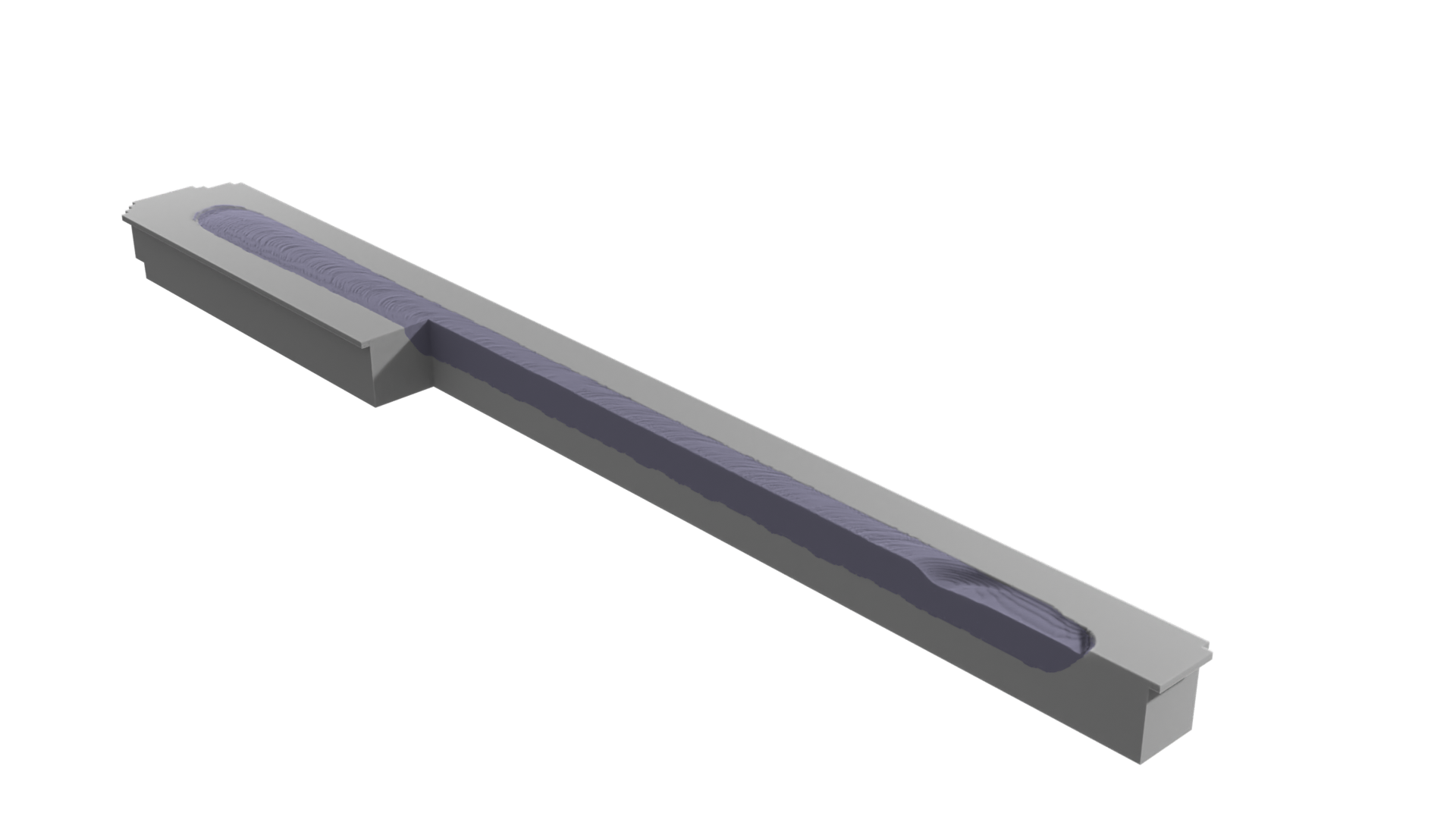
Fig. 44 openVDB file loaded and rendered in Blender
Images and animation output
The meltpool states are rendered as images and stored in output/rendered3D.
The images of cross-sections are found in output/cross-sections.
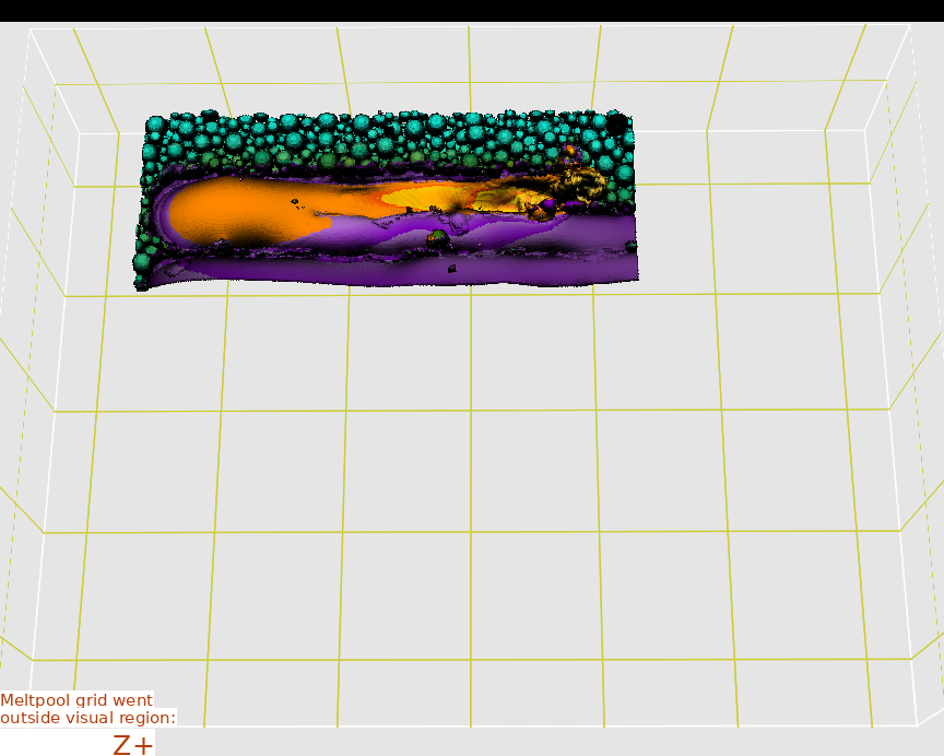
Fig. 45 Example of the combined image combinedIMG/pic-250000.png
Surface analysis
In the simulation folder, run the script generating file geometry data in text format:
> /opt/KiSSAM/scripts/surfaceAnalyzer.x output/geometry.vdb > heights.dat
The output is the text file heights.dat.
#units: millimeters
#Xcoord Ycoord SurfaceHeight MeltpoolDepthPosition
0 0 4.56 4.56
0.003 0 4.56 4.56
0.006 0 4.56 4.56
0.009 0 4.56 4.56
0.012 0 4.56 4.56
0.015 0 4.56 4.56
0.018 0 4.56 4.56
0.021 0 4.56 4.56

...
Here we plot the third and the fourths columns as a colormap
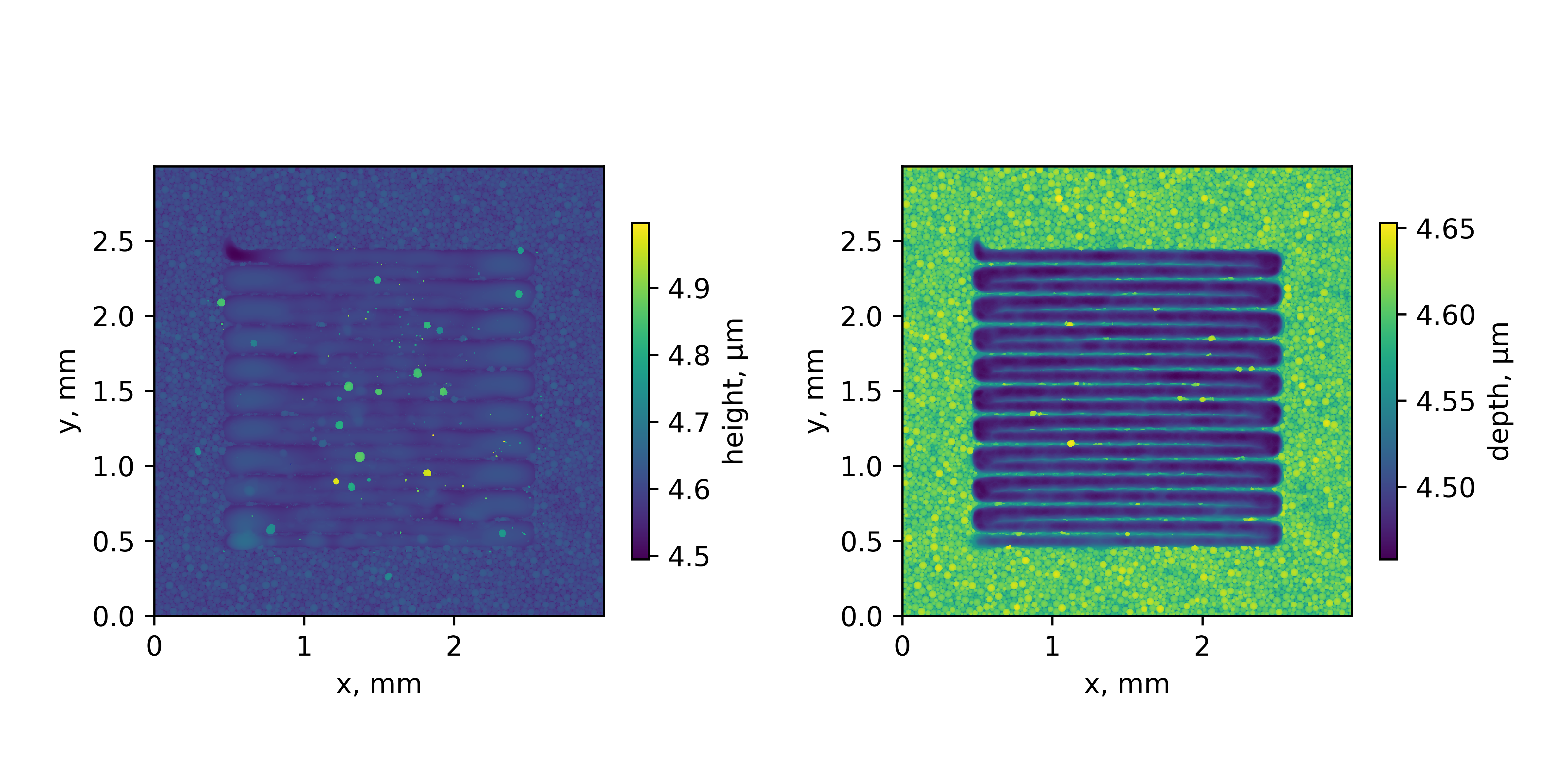
Fig. 46 Surface information plotted in the xy plane
Cross Section Image
Let us run this script to extract cross-section at \(x=1.5\) mm from the track start startPosX (\(1\) mm):
> /opt/KiSSAM/scripts/drawCrossSection.x output/geometry.vdb trackXcrossSection.png --box 2.5,1.91,4.4867 2.5,2.09,4.6 --background E8F0F200 --substrate 295569FF --remelted CD86F2FF
One pixel of the image is one mesh step: NumericalParams.dr (3 μm) in the input file.

Fig. 47 Cross section in simulation