
Microstructure Simulation
Introduction
Grain growth during solidification is modeled using Cellular Automata (CA), as described in the paper by Lian et al. [lian2018parallelized].
To enable the simulation of grain growth, set config.calcGrains to true.
The simulation consists of two main stages: initialization of grains in the substrate and/or powder (if necessary), and the actual grain growth during solidification.
Yanping Lian et al. “A parallelized three-dimensional cellular automaton model for grain growth during additive manufacturing”. In: Computational Mechanics 61 (2018), pp. 543-558
Parameters Overview
The parameters in the JSON file that are used in the grain growth simulation are:
In the
configsection:
config.CalcGrains
config.SolidificationCriterion
config.StopIfGrainsLimitBoxReachedIn the
sizessection:
sizes.GrainsLimitBoxIn the substrate and the powder settings:
Substrate.initialNucleiDensity
Powder.initialNucleiDensityIn the material description:
Grainssection
Grains Setup
Initial grains in the substrate can be generated automatically inside the Grains Limit Box during initialization if necessary, or loaded from the previous layer in multilayer simulations.
Grain initialization in the substrate will be performed if the Substrate.initGeometryVDBfile field is empty.
or, if it is not empty, it the substrate is given as a VDB file which does not contain a grid named GrainsType.
Otherwise, grains are initialized inside a virtual box with sizes specified by the parameter sizes.GrainsLimitBox.
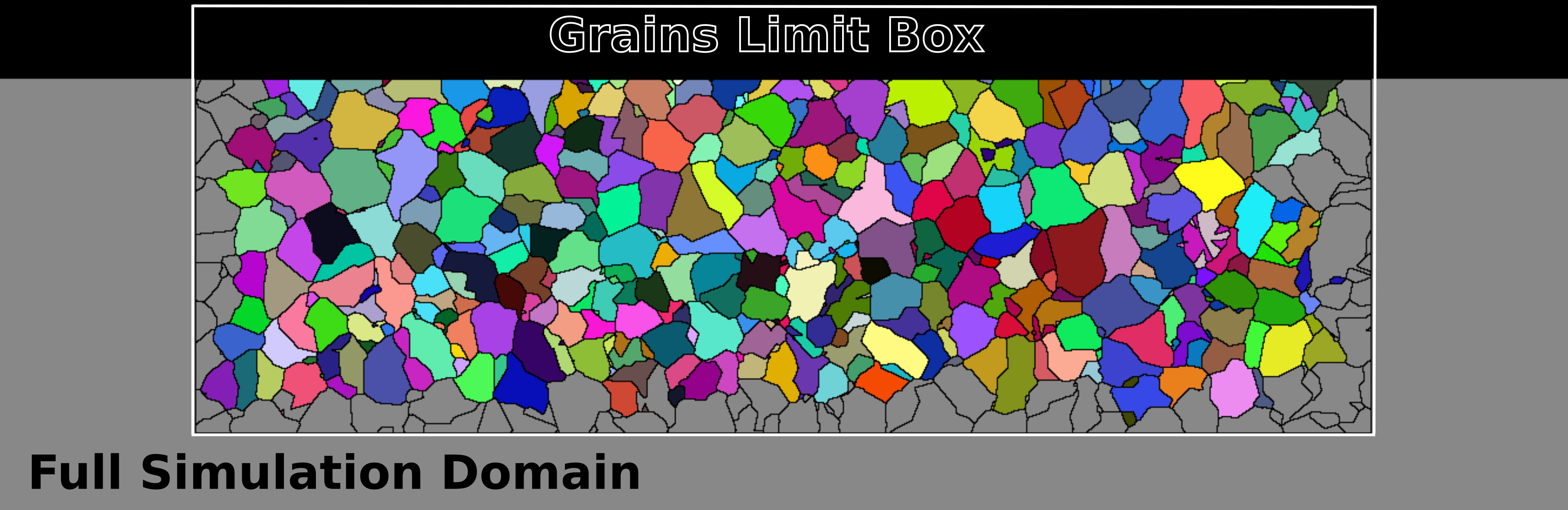
Fig. 15 Cross-section of the initial grain structure in the substrate. Each grain is depicted with a different color. The external region and grains extending beyond the limit box are grey.
If the parameter config.StopIfGrainsLimitBoxReached is set to true, the simulation will terminate immediately after the melt pool reaches the grain limit box boundary.
The initial nuclei density in the substrate is specified by the parameter Substrate.initialNucleiDensity (\(m^{-3}\)),
and the average grain volume is \(1/\texttt{Substrate.initialNucleiDensity}\).
The initial nuclei density in the powder is set by the parameter Powder.initialNucleiDensity (\(m^{-3}\)).
Note that the grain size cannot be larger than a single powder particle.
All powder particles have different grains at the initialization if the parameter Powder.initialNucleiDensity is small enough.
The default value for Powder.initialNucleiDensity is 0, i.e., each powder particle consists of one grain.
In the simulation, the solidification can be performed either when the temperature falls below the threshold value (in the fluid model), or when the grain growth is completed (in the CA model).
To solidify when the temperature falls below \(T_\text{solidus}\) set the config.SolidificationCriterion parameter to "Temperature".
To solidify when the grain growth is fully completed in a cell and it becomes solid according the grains CA algorithm set config.SolidificationCriterion to "GrainsCA".
Nucleation
If the config.calcGrains parameter is set to true,
the material in use must contain the Grains section.
This section must have all necessary parameters, as shown in the example below:
{
 ...
 "MaterialsLibrary": {
    ...
    "MyNewMaterial": {
        ...
        "Grains": {
            "GrowthCoeffs"  : [1.8e-5, 1.6e-5, 2.3e-6],
            "Nucleation"    : {
                "Bulk"   : {
                    "Density": 1e15,
                    "CriticalTdiff": [9.5,0.5]
                },
                "Surface": {
                    "Density": 2.5e8,
                    "CriticalTdiff": [2,0.1]
                }
            }
        }
    }
}
The grain growth velocity (m/s) is \(v = K_1 \Delta T + K_2\Delta T^2 + K_3\Delta T^3\) , where the coefficients \(K_1\) is in m/s/K, \(K_2\) is in m/s/K \({}^2\), \(K_3\) is in m/s/K³ and the temperature difference \(\Delta T = \max(T_{liquidus} - T, 0)\) is in K.
New grains can appear from nucleation during solidification. There are two types of nucleation: new nuclei can appear in the liquid material (homogeneous bulk nucleation) and on the surface. The nucleation density has a Gaussian distribution formed from undercooling \(\Delta T\) and follows the law:
The user must specify the values for both the bulk nucleation and the nucleation on the surface: \(n_\text{max}\) in \(\text{m}^{-3}\), \(\overline{\Delta T}\), and \(\Delta T_\sigma\) in K. Specifically:
MaterialsLibrary.MyMaterial.Grains.Bulk.Densityis \(n_{max}\) for the bulk nucleation,
MaterialsLibrary.MyMaterial.Grains.Bulk.CriticalTdiffis \([\overline{\Delta T}, \Delta T_\sigma]\) for bulk;
MaterialsLibrary.MyMaterial.Grains.Surface.Densityis the \(n_{max}\) for the surface nucleation,
MaterialsLibrary.MyMaterial.Grains.Surface.CriticalTdiffrepresents \([\overline{\Delta T}, \Delta T_\sigma]\) for the surface nucleation.
Results
After the simulation, the results of the grains growth is written to the geometry.vdb file.
It is a file in the openVDB format which can be opened with third party software such as ParaView or blender.
When the grain growth is simulated, in the file, the are two additional grids for grains:
GrainsDirectioninteger vector values
GrainsTypeinteger vales
You can use the script drawCrossSection.x script which comes with KiSSAM to get the cross-section images with the grain structure.
For example, if the scanning strategy is set to single track with starting position \(y=0.0005\):
>./drawCrossSection.x geometry.vdb ysec1-grains.png --sec y 0.5 --grains
Or, to highlight grain boundaries
>./drawCrossSection.x geometry.vdb ysec1-grains.png --sec y 0.5 --grains --hl_bound_grains