
Channel in a printed part (success)
Introduction
In the previous example the channel in a printed part is not formed. This example shows a successful manufacturing of a part with a small channel.
Input
The printing is performed by hatching multiple layers. The hatching strategy for the dense sample is imported from the g-code files.
The cavity is formed by turning the laser off when the laser spot is in the specified coordinate range. This ability is not supported by the user interface. At present, the users are advised to prepare g-code files which include the cavity.
Here is the configuration for the simulation:
{
  "Material": "SS316L",
  "NumericalParams": {
     "dr" : 4e-6,
     "dt" : 40e-9
  },
  "ScanStrategy": {
    "Beam": {
      "Power": 250.0,
      "Speed": 1.200,
      "Width": 80e-6,
      "type": "Laser"
    },
    "Type": "Manual"
  },
  "config": {
    "MemoryAllocation"     : "managed",
    "AutoTermination": true,
    "DumpARR": false,
    "DumpVTK": true,
    "IterationSubstepsRate": 1000,
    "DumpDataRate": 10000,
    "MaxTimesteps": 22000000,
    "calcBubbles"          : true,
    "AllowToRunoutXYbox"   : true
  },
  "sizes": {
    "FullXapprox": 0.003,
    "FullYapprox": 0.003,
    "FullZapprox": 0.004,
    "substrate": 0.003
  },

  "Visual": {
  "distanceBetweenXsecs": 80e-6,
  "3DrenderedDomainSize": [2.2e-3, 2.2e-3, 0.6e-3],
  "BeamToBoxMinDistanceX": 200e-6,
  "BeamToBoxMinDistanceY": 200e-6
  },
  "Powder": {
    "initSpheresVDBfile": "",
    "components"             : null
  },
  "Substrate": {
    "preheating"  : 300.0,
    "wettingAngle": 0,
    "components"             : null
  },
  "PowderBedGenerator": {
    "Type": "PowDEM",
    "RandomSeed":0,
    "GroundSurface": "",
    "PSDsizes": [
      [0,10.756e-6],
      [0.030,12.084e-6],
      [0.090,13.577e-6],
      [0.414,15.254e-6],
      [1.058,17.138e-6],
      [2.555,19.255e-6],
      [5.302,21.633e-6],
      [9.769,24.305e-6],
      [16.721,27.307e-6],
      [25.676,30.680e-6],
      [36.794,34.469e-6],
      [48.913,38.727e-6],
      [61.238,43.510e-6],
      [72.825,48.885e-6],
      [82.492,54.923e-6],
      [90.162,61.707e-6],
      [95.099,69.328e-6],
      [98.062,77.892e-6],
      [99.316,87.513e-6],
      [99.596,98.322e-6],
      [99.703,110.467e-6],
      [99.722,139.441e-6],
      [99.740,156.665e-6],
      [99.783,176.016e-6],
      [99.840,197.757e-6],
      [99.915,222.183e-6],
      [99.980,249.627e-6],
      [99.999,280.460e-6],
      [100,315.102e-6]
    ],
    "PSDtype": "Volume",
    "SurfaceVerletSizeCalc": "Ball",
    "KnifeZposition": 0.003050
  },
  "G-code-converter": {
    "idleSpeed": 7000,
    "workSpeed": 1200,
    "offset": [3,3]
  }
}
Results
The simulation is performed with KiSSAM (“commit_info” => “cba4f87 Thu Feb 22 15:49:21 2024 +0300”).
The images are rendered with blender.
To mark different layers with different colors, the mergeLayers script with the --secern option is used.
for n in {1..11}; do /opt/KiSSAM/scripts/mergeLayers.x $(seq -f 'geometry%02.f.vdb' $n) --out HoleB-$n.vdb --secern; done

Fig. 68 Layer 1. A square layer is hatched. The geometry shows some flying droplets. They are removed from the geometry before depositing the next powder layer.
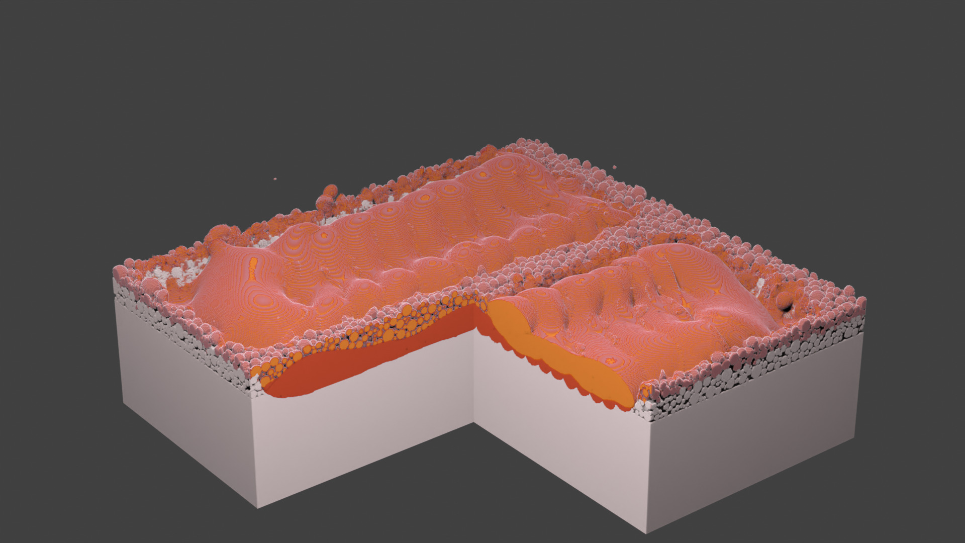
Fig. 69 Layer 2. Laser does not scan the center area starting from this layer.
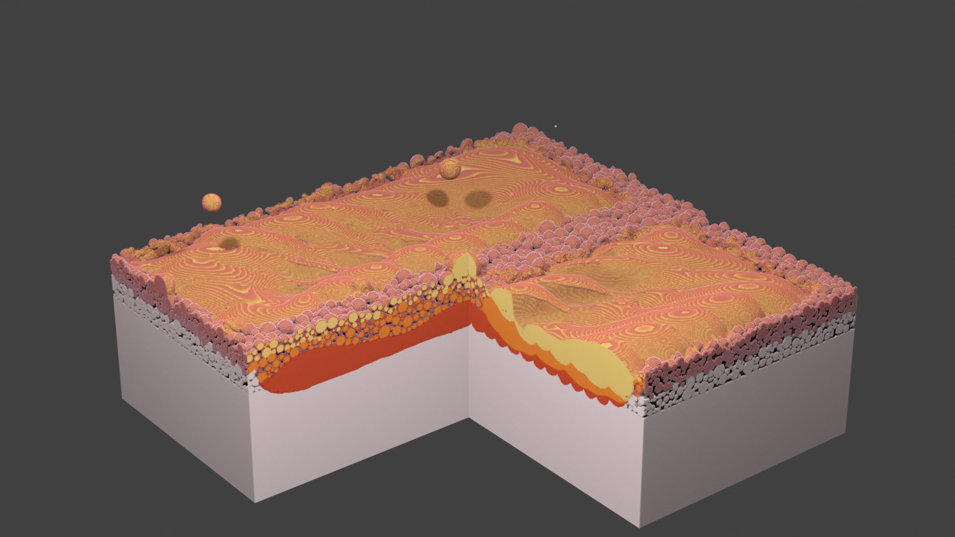
Fig. 70 Layer 3. A droplet lands in the channel.
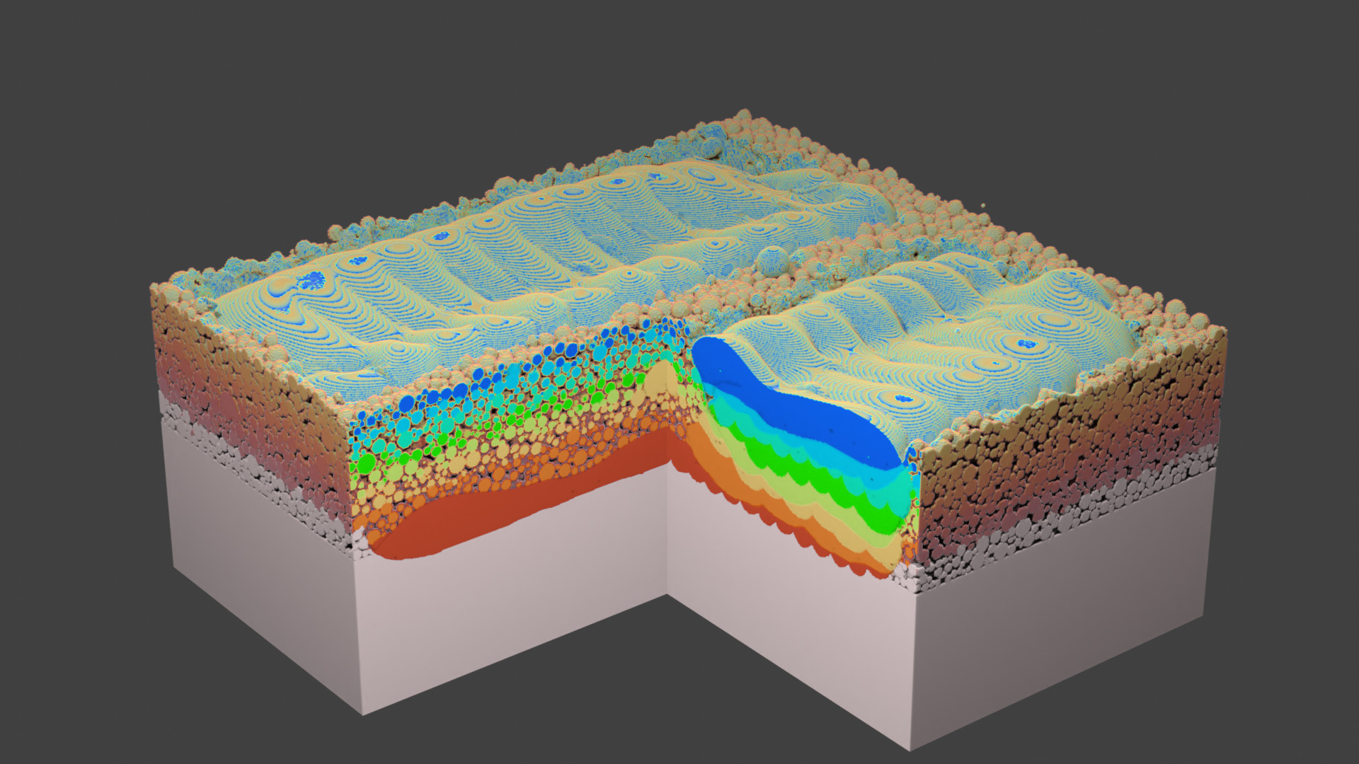
Fig. 71 Layer 8.
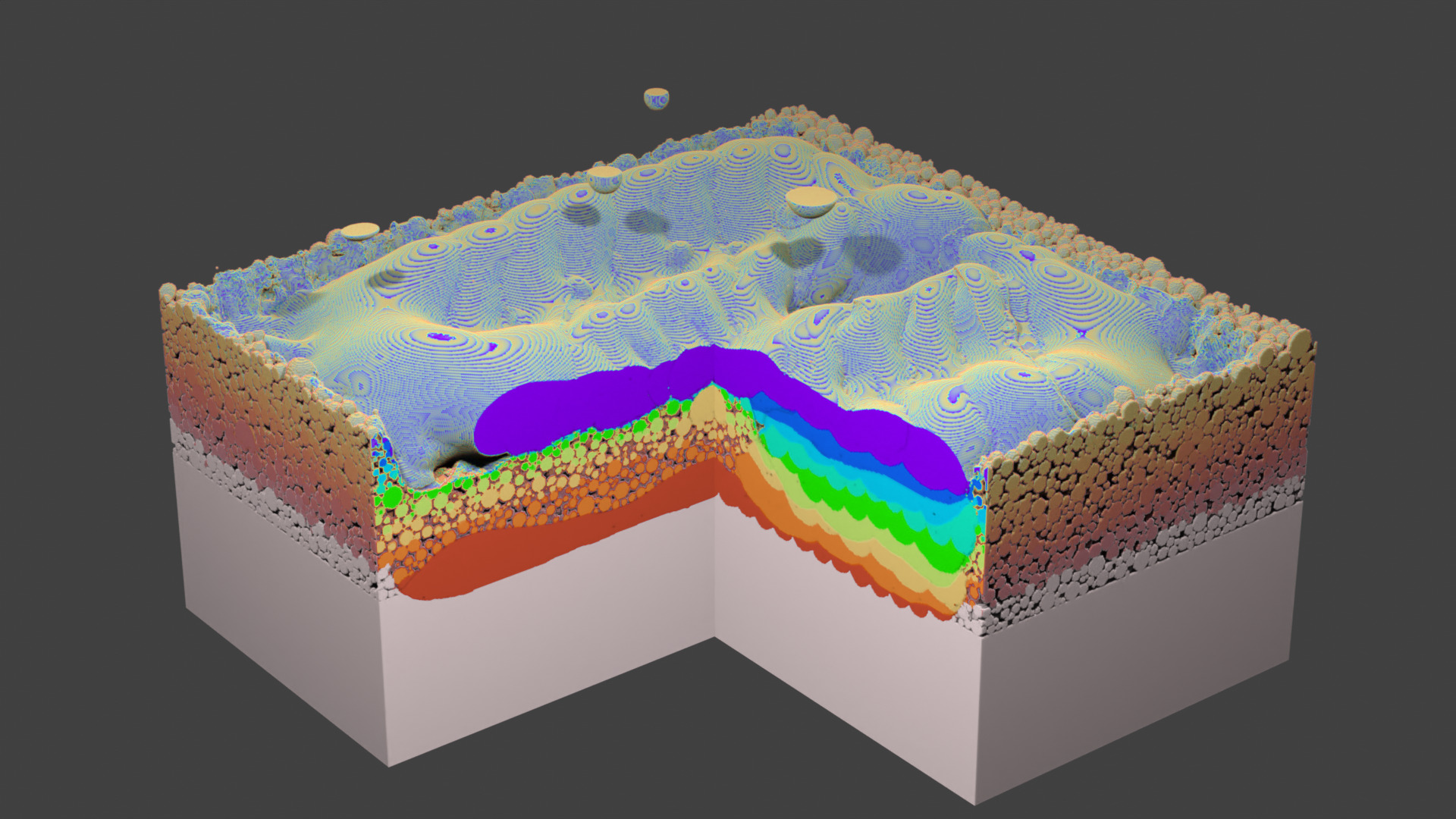
Fig. 72 Layer 9. From here on, the whole square is hatched to close the channel.
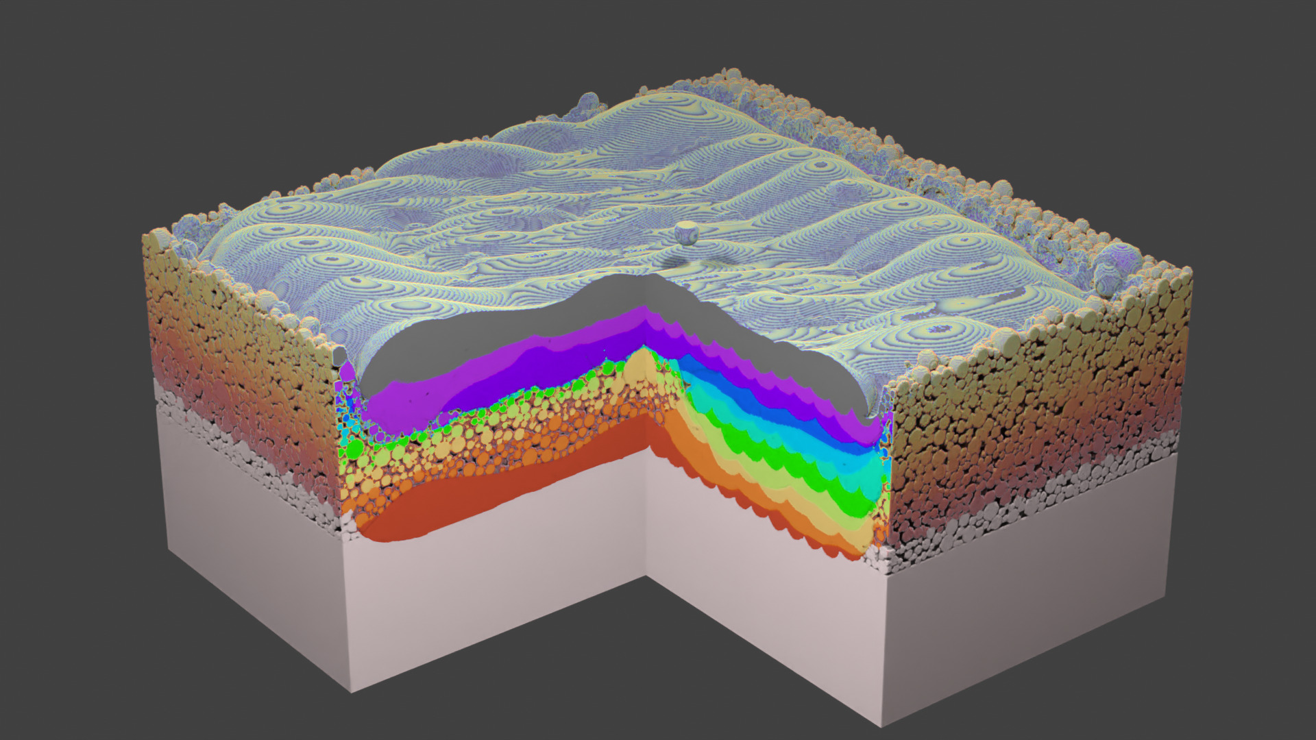
Fig. 73 Layer 11. Final layer of the current simulation.
Fig. 74 Animation.
Finally, we use the Remove Powder script to isolate the printed part. The powder particles, which were not melted in the process, are deleted.
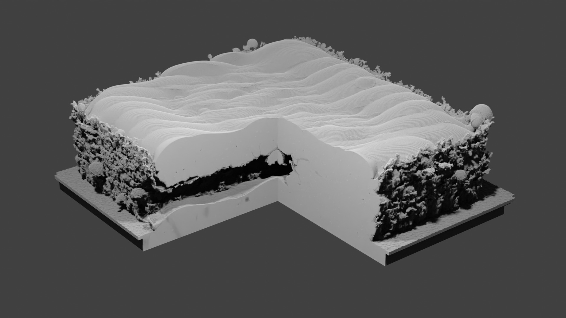
Fig. 75 Isolated part. The channel is formed. However, there is an obstruction in the channel from the droplet that landed in the center during the third layer melting.
Timing
The simulation is performed on nVidia GeForce RTX 4090. Powder deposition usually takes under 2 hours, melting of one layer is under 24h. The total simulation took under 2 weeks.